

A simple solar boost converter and voltage limiter circuit that charges a 12V battery from a 6V solar panel with MPPT (Maximum Power Point Tracking) capability.
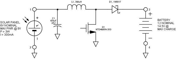
fig 1. boost switching converter topology
fig 2. charging and discharging waveform
Here inductor L1 (390 uH) charges when Q1(NTD4906N-35G) turns on. When Q1 turns off, L1 discharges into the battery via D1(IN5817). Performing this simple operation thousands of times per second results in appreciable output current. It is also called inductive discharge. For this to function, the input voltage must be lower than the output voltage. Also, with a solar panel source, energy storage in the form of a capacitor (C1- 470uF/25v) is required so that the solar panel can continue to output current between cycles.
Actual Complete Circuit: BOOST MPPT SOLAR POWER CONTROL
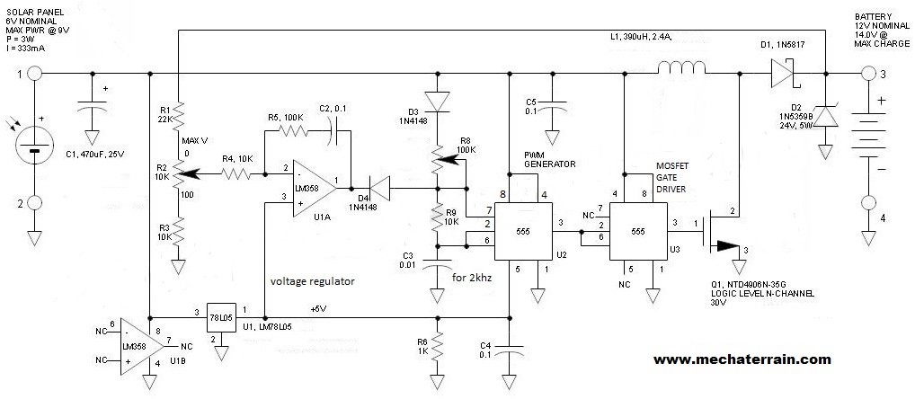
This circuit is designed for a 9V, 3W solar panel. To apply the same circuit for different rating of solar panel it is required that u change the value of inductance L1 and the value of C3. To obtain best results of the circuit , charge the inductor to about 5 to 10 times the solar panel current, and then allow an extended period of time (3X) for the inductor to completely discharge. This allows for acceptable operation when the source gets close to the battery voltage.
Component list:
- solar panel: 9V,3W
- C1: 470uF/25v, C2: 0.1uF, C3: 0.01uF, C4: 0.1uF, C5: 0.1uF
- R1:22k, R2:10k, R3:10k, R4:10k (pot), R5:100k, R6:1k, R8: 100k (pot), R9:10k
- D1: 1N5817, D2: 1N5359, D3: 1N4148, D4: 1N4148
- L1: 390 uH, Q1: NTD4906N-35G, U1 A: LM358, U1 B: LM358 , U1: LM7805, U2: 555, U3:555
Working
The circuit consists of essentially three sections including a 555 MOSFET gate driver, 555 PWM modulator and op amp voltage limiter. The 555 with its totem pole output can source as well as sink roughly 200mA and makes a great low power gate driver. The 555 PWM modulator is the classic 555 oscillator circuit. To regulate the C3 discharge time (inductor charge time), pin 5 is held at a regulated 5V. Op amp U1A integrates the battery voltage signal when the divided set point voltage is compared with the 5V reference. When the voltage exceeds the setting, the output integrates in the negative direction thus reducing the repetition rate of the PWM generator and limiting any subsequent charging. This effectively prevents overcharging. To prevent unnecessary battery discharge when the sun is not shining, all circuitry is powered via the solar panel. The one exception is the voltage feedback divider that draws approximately 280uA. Since the circuit must operate at low voltages (this one works down to about 4V input) a logic level MOSFET is required. It turns on at fully at 4.5V
Function of MPPT (Max Power Point Tracking):
As the solar panel voltage /current increases, the PWM generator increases its repetition rate thus resulting in increased output current. At the same time, additional voltage is applied to the inductor thus increasing its charge current. As a result, the boost regulator really digs in as the voltage increases, or lets up as the voltage diminishes. To achieve maximum transfer of power with full sunlight, potentiometer R8 is adjusted so that the battery charging current is maximized this is known as the maximum power point. If the circuit is operating properly, there will be a very shallow peak as R5 is rotated. Diode D3 makes the automatic MPPT adjustment function more sensitive by subtracting a fixed voltage from the voltage difference between the battery and the average voltage across C3. Under lower light conditions, you will find that R3 is not exactly at optimum, but it will not be significantly off.
Category:


