
the basic relationship between the machine geometry and the part setup was discussed. CNC programmers work in a fairly precise environment, and mathematical relationships are of extreme importance.There are three major environments in programming that require an established mathematical relationship:
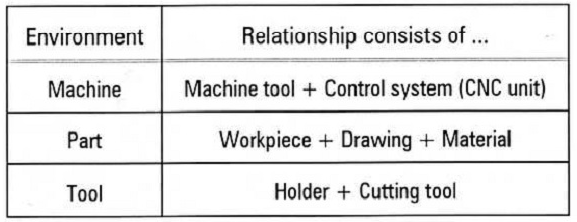
These sources inevitably meet when a customer buys a CNC machine. A certain engineering design (part), must be machined on a machine tool from one manufacturer, using a control system of another manufacturer, cutting tools from yet another manufacturer, and tool holders from a fourth source. These sources are similar to a musical quartet of first class musicians who never played together. In both cases there is a need to create a harmony
By itself, each environment is not very useful. A machine without tools will not yield any profit; a tool that cannot be used on any machine is not going to benefit the manufacturing either. A part cannot be machined without tools.
The common point here is that all three environments cannot be useful without some 'team work'. They have to work together, they have to interact. For programming purposes, these relationships and interactions are based on one common denominator of each environment - a reference point.
A reference point is a fixed or selected arbitrary location on the machine, on the tool and on the part. A fixed reference point is a precise location along two or more axes, designed during manufacturing or setup. Some reference points are established by the programmer, during the programming process. In these three environments, three reference points are needed - one reference point for each of the available groups:
Machine reference point .. Machine zero or Home
Part reference point .. Program zero or Part zero
Tool reference point .. Tool tip or Command point
In a typical language of a machine shop, these reference points have somewhat more practical meaning. Home position or a machine zero are synonymous terms for machine reference point. A program zero, or part zero, or part origin are terms commonly used instead of the more official term part reference point. And the name tool tip or a tool command point are commonly used for the tool reference point.
REFERENCE POINT GROUPS
The first group is the CNC machine tool or CNC machine for short, which is the combination of machine proper and the control system. The numeric values that relate to the CNC machine tool include a variety of dimensions, specifications, parameters, ranges, ratings, etc. When a part is set in a fixture on the machine table or mounted into a lathe chuck, collet, face plate, or other work holding device, there is a second group of numbers to consider. The part considerations, such as its size, its height, diameter, shape, etc., are unique to each job. Finally, the third group of numbers relate to the cutting tools. Each cutting tool has its individual features, as well as features that are shared with the other cutting tools.
All available numeric values have a meaning - they are not merely numbers - they are actual values that program-mers and operators have to work with individually as well as together.
• Reference Point Groups Relationship
The key to any successful CNC program is to make all three groups to work in a coordinated way. This goal can only be achieved by understanding the principles of reference points and how they work. Each reference point can have two characteristics:
• Fixed reference point
•Flexible or floating reference point
A fixed reference point is set by the machine manufacturer as part of the hardware design and cannot be physically changed by the user. A CNC machine has at least one fixed reference point. When it comes to deciding the reference points for the part or the cutting tool, the programmer has certain degree of freedom. A part reference point (program zero) is always a flexible point, meaning its actual position is in programmer's hands. The reference point for the mounted cutting tool can be either fixed or flexible, depending on machine design.
MACHINE REFERENCE POINT
The machine zero point, often called the machine zero, home position or just a machine reference position, is the origin of machine coordinate system. The location of this point may vary between the machine manufacturers, but the most obvious difference is between individual machine
In general terms, a CNC machine has two, three, or more axes, depending on the type and model. Each axis has a maximum range of travel that is fixed by the manufacturer. This range is usually different for each axis. If the CNC operator exceeds the range on either end, an error condition known as overt ravel will occur. Not a serious problem, but one that could be annoying. During machine setup, particularly after the power has been turned on, the position of all axes has to be preset to be always the same, from day to day, from one part to another. On older machines, this procedure is done by setting a grid, on modern machines, by performing a machine zero return command. Fanuc and m4iy other control systems prevent automatic operation of a machine tool, unless the machine zero return command has been performed at least once - when the power to the machine has been turned on. A good safety feature.
On all CNC machines that use typical coordinate system, the machine zero is located at the positive end of each axis travel range. For a typical three-axis vertical machining center, look at the part in the XY plane, that is straight down from the tool position (tool tip). Also look into the XZ plane (operator's front view of the machine), or into the YZ plane (operator's right-side view of the machine). These three planes are perpendicular to each other and together create so called work cube or work space - Figure .
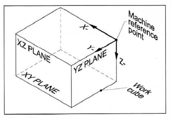
The cubical shape shown is useful only for overall understanding of the machine work area. For programming and setup, the majority of work is done with one or two axes at a time. To understand the work area and machine zero point in a plane, look at the machine from the top (XZ machine plane) and from the front (YZ machine plane). Figures illustrate both views.
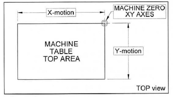
Compare the two views. In top view, the upper right cor-ner is also the spindle center line shown in the front view. Also note that in front view, there is a dashed line identified as the gauge line. This is an imaginary location for the proper fit of the tool holder tapered body and is set by the machine manufacturer. The inside of the spindle is a precision machined taper that accepts the tool holder with the cutting tool. Any tool holder mounted in the spindle will be in exactly the same position. The Z motion illustrated will be shortened by the cutting tool projection. This subject of tool referencing is discussed later in this article.
Category:


