
Coordinate Geometry Basics

G - Code Programming G – Code Programming originally called the “Word Address” programming format. Processed one line at a time sequentially.

Reserved Code Words Worksheet
N – Sequence or line number
G – Preparatory function
Word Address 1
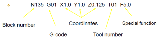
N – (Sequence or line number) A tag that identifies the beginning of a block of code. It is used by operators to locate specific lines of a program when entering data or verifying the program operation.
G – (Preparatory function) “G words” specify the mode in which the milling machine is to move along its programmed axes.
Word Address 2
Dimension Words: - X – Distance or position in X direction
Y – Distance or position in Y direction
Z – Distance or position in Z direction
M – Miscellaneous functions M words specify CNC machine functions not related to dimensions or axial movements.
Word Address 3
F – Feed rate (inches/minute or millimeters/ minute) “Rate at which cutting tool moves along an axis.”
S – Spindle speed (rpm – revolutions per minute) “Controls spindle rotation speed.”
T – Tool number (Specifies tool to be selected.)
Word Address 4
I – Circular cutting reference for x axis
J – Circular cutting reference for y axis
K – Circular cutting reference for z axis
G Words: - G words or codes tell the machine to perform certain functions. Most G words are modal which means they remain in effect until replaced by another modal G code.
CNC Programming Basics
- CNC instructions are called part program commands.
- When running, a part program is interpreted one command line at a time until all lines are completed.
- Commands, which are also referred to as blocks, are made up of words which each begin with a letter address and end with a numerical value.
“G” AND “M” CODES
- Each letter address relates to a specific machine function. “G” and “M” letter addresses are two of the most common. A “G” letter specifies certain machine preparations such as inch or metric modes, or absolutes versus incremental modes.
- An “M” letter specifies miscellaneous machine functions and work like on/off switches for coolant flow, tool changing, or spindle rotation. Other letter addresses are used to direct a wide variety of other machine commands.
CNC programming Important things to know:-
- Coordinate System
- Units, incremental or absolute positioning
- Coordinates: X,Y,Z, A,Y,Z
- Feed rate and spindle speed
- Coolant Control: On/Off, Flood, Mist
- Tool Control: Tool and tool parameters
- Programming consists of a series of instructions in form of letter codes
- Preparatory Codes:
- G codes- Initial machining setup and establishing operating conditions
- N codes- specify program line number to executed by the MCU
- Axis Codes: X,Y,Z - Used to specify motion of the slide along X, Y, Z direction
- Feed and Speed Codes: F and S- Specify feed and spindle speed
- Tool codes: T – specify tool number
- Miscellaneous codes – M codes For coolant control and other activities
Programming Key Letters
- O - Program number (Used for program identification)
- N - Sequence number (Used for line identification)
- G - Preparatory function
- X - X axis designation
- Y - Y axis designation
- Z - Z axis designation
- R - Radius designation
- F – Feed rate designation
- S - Spindle speed designation
- H - Tool length offset designation
- D - Tool radius offset designation
- T - Tool Designation
- M - Miscellaneous function
BASIC CNC PROGRAMMING PART
COMMON G-CODES
G00 – Rapid positioning mode Tool is moved along the shortest route to programmed X,Y,Z position. Usually not used for cutting.
G01 – Linear Interpolation mode Tool is moved along a straight-line path at programmed rate of speed.
G02 – Circular motion clockwise (cw)
G03 – Circular motion counter clockwise (ccw)
G17 – XY plane
G18 – XZ plane
G19 – YZ plane
G20 – Inch Mode
G21 – Metric Mode
G28 – Return to axis machine Zero (Home)
G90 – Absolute Coordinate Reference References the next position from an absolute zero point which is set once for the entire program.
G91 – Incremental Coordinate Reference References the next position from the previous position.
G-CODES FOR CANNED CYCLES
G80 – Cancel canned cycle
G81 – Drilling cycle
G83 – Peck drilling cycle
G84 – Tapping cycle
G85 – Boring cycle
G86 – Boring cycle (NOTE: A canned cycle stays in effect until cancelled by a G80.)
G Codes: Cutter Compensation
G40 – Cancel cutter diameter compensation.
G41 – Cutter compensation left.
G42 – Cutter compensation right.
Here is the list of some G-codes which can be used as per their need
Note: - Not all the G-codes apply to each machine. And some of the G-codes can be assigned as per usage.
Some of M-codes (miscellaneous code)
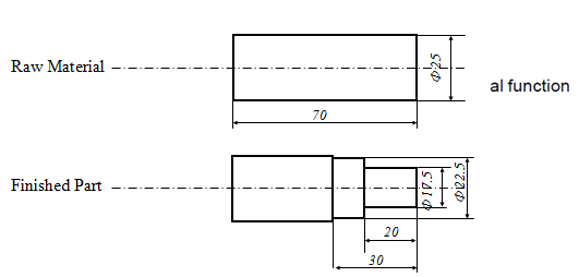
Programming Example using G-codes:-
O0013 ⇒ Program identification number
N0005 G53 ⇒To cancel any previous working zero point
N0010 T0303 ⇒ Sequence number, Tool number
N0020 G57 G00 X26.00 Z0.0 S500 M04
N0030 G01 X-0.20 F100
N0040 G00 Z2.0
N0050 X50.0 Z50.0
N0060 T0404
N0070 G57 G00 X22.50 Z2.0 S500 MAIN PROGRAM
N0080 G01 Z-30.0 F100
N0090 G00 X23.0 Z2.0 S500
N0100 G84 X17.5 Z-20.0 D0=200 D2=200 D3=650
N0110 G00 Z2.0
N0120 X50.0 Z50.0
N0130 M30 ⇒END PROGRAM
After this the work done on the work piece by the machine is
VIDEO
Category:


Comments
Nice tutorial anurag
Nice tutorial anurag
great....thanx..it helped me
thanks helping a lot